 MP4 | Video: h264, 1280x720 | Audio: AAC, 48 KHz, 2 Ch
Genre: eLearning | Language: English + .SRT
Level: Intermediate | Duration: 1h 22m | 234 MB
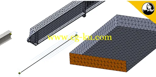
Much of CAD design uses 3D elements for finite element analysis (FEA) simulation. However, sometimes thin-walled or frame-like structures dominate. In these cases, shell (2D) and beam (1D) elements can represent designs more effectively. Across all industries, as much as 50% of the design of major engineering projects fall into these categories.
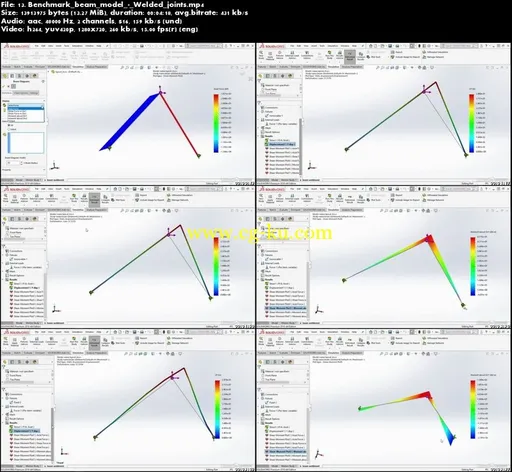
In this course, instructor Tony Abbey explains how to work with shell and beam models in SOLIDWORKS. Learn when to use shell, beam, and specialized truss elements; understand the fundamentals of modeling with them; and find out how to mesh, postprocess, and model components with these tools. Tony shows how to set up and run these FEA simulations to test the integrity of your designs and view results such as stress, force, and displacement.
Topics include:
Modeling beams and trusses
Using weldments
Modeling shells
Using surfaces
Using solid bodies
Using sheet-metal bodies
Setting up and running FEA simulations

Password/解压密码
-0daydown


发布日期: 2018-09-21